How To Roll Sheet Metal In Inventor

Inventor Sheet Metal Cylinder Tutorial With Contour Roll Command Youtube

Autodesk Inventor Sheet Metal Design Tutorial Contour Flange Youtube
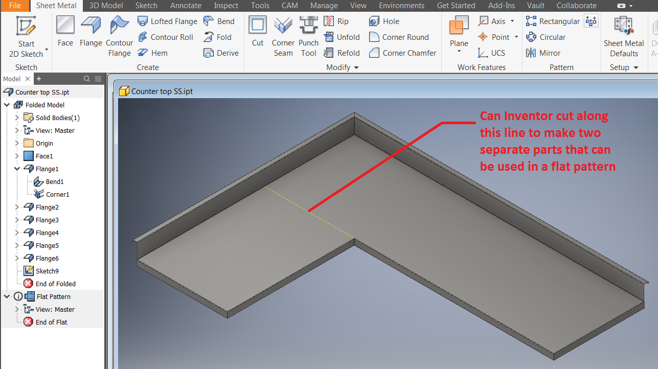
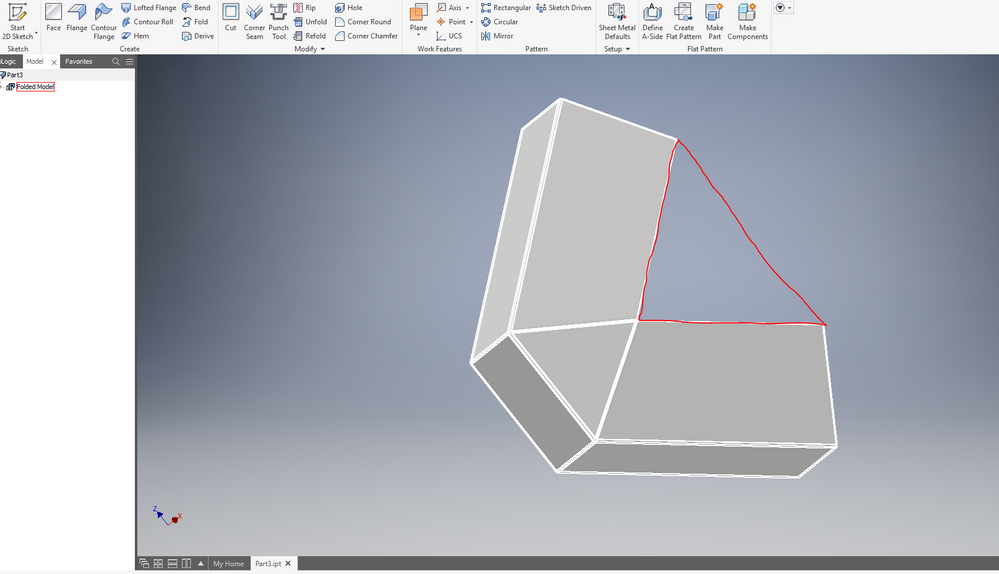
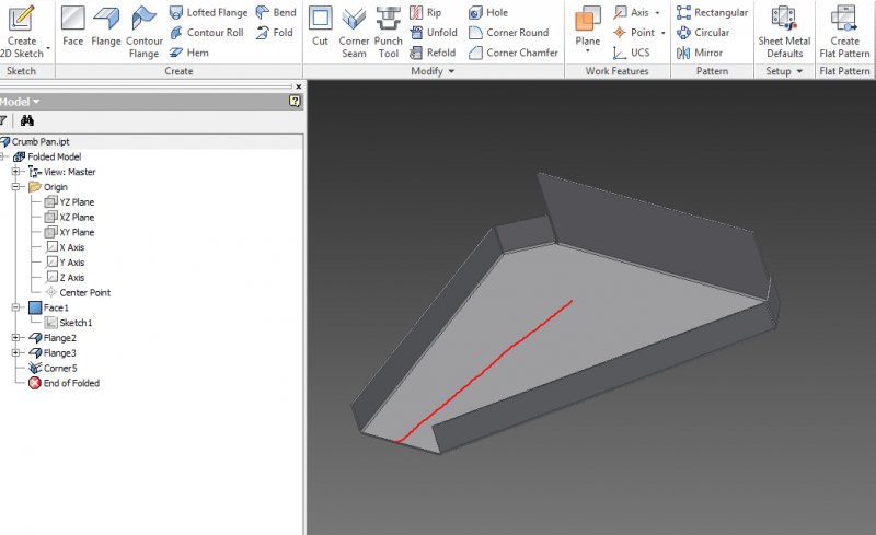
How To Split A Sheet Metal Part While Keeping The Ability To Create A Flat Part In Inventor Inventor 2019 Autodesk Knowledge Network

Autodesk Inventor 2010 Sheet Metal Design Youtube

Inventor Sheet Metal Contour Rolls As Secondary Features Youtube

Autodesk Inventor Sheet Metal Design Youtube
In this tutorial we are going to discuss about the contour roll tool in detail.
How to roll sheet metal in inventor.
How To Bend Or Fold Sheet Metal Autodesk Inventor Autocad Forums

Inventor Holes In A Sheetmetal Curve Youtube

Inventor Sheet Metal Contour Flange Tutorial Youtube

To Work With Contour Rolls In Sheet Metal Inventor 2019 Autodesk Knowledge Network
Source : pinterest.com
